
This weekend I took a deep breath and started laying the track for my APA box layout.
To fit the layout inside the box the curves need to be 127mm (5 inch) radius – pretty tight.
I’d read there are two tricks to tight curves:
- Start at the apex of the curve
- Keep the track flat on the baseboard as you bend it
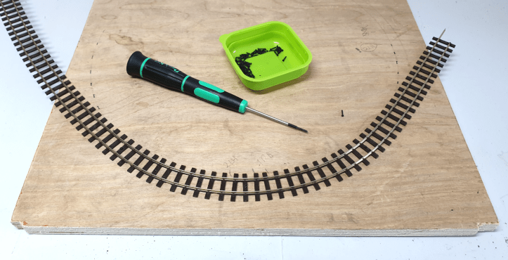
I followed the advice. The photo at the beginning of the blog shows the start of the curve at the apex.
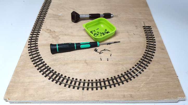
Here’s a photo after some progress….
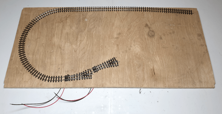
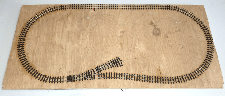
…and this photo shows the finished curve.
By following the advice it is relatively easy to curve unmodified Peco OO9 track around a tight curve. (The straight track to the left hasn’t been fixed in place yet).
You’ll see I used 6mm track screws to hold the track in place. I find these much easier to use than track pins. I pre-drilled a hole in every fourth sleeper and gently curved the track. I positioned a pre-drilled sleeper, drilled a shallow hole in the baseboard to help hold the screw in place, then screwed the track into position.
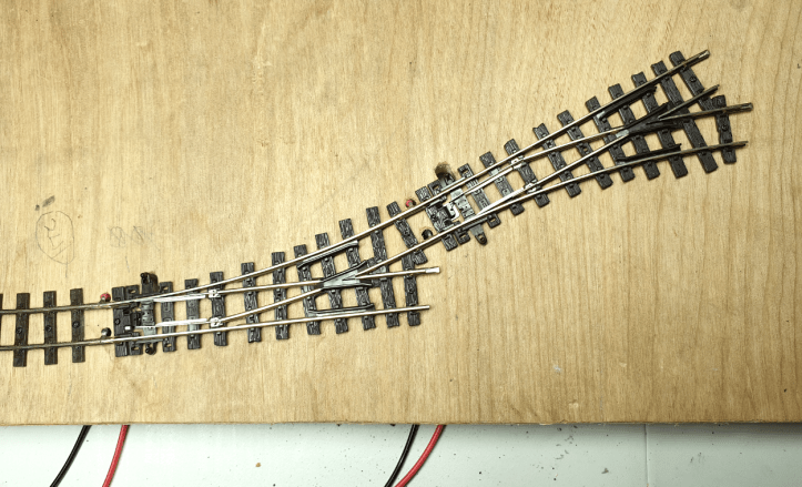
Next job was to install the points (switches). This was easier than the curve!
As space is limited I used Peco OO9 settrack turnouts (ST405 and ST-406). I installed electrical feeds to the ‘toe’ of each point using Peco Power Feed Joiners (PL-82). I brought a pack of 8 feeds in a model shop for £7.50. At less than £1 per feed it didn’t seem worth making my own.
After a rest, a cup of coffee and a biscuit I completed the circuit of track by running one piece of OO9 flexitrack around the right hand end of the layout and joining it to the first piece of track. I installed another pair of power feeds at the join. It was easy to do and it seemed sensible to have another power input.
Underneath the baseboard I attached the wires to a ‘Plug and Socket Terminal’. This made it easy to connect my controller. I may change the wiring at a later date. Or I may not. It’s a simple approach, why make it more complicated ? 🙂

The track was cleaned with a track rubber and a Kato 11-107 chassis used for the testing.
I’m pleased to say it worked first go. Hurrah!
Here’s a video of the test.
To create a ‘shunting puzzle’, two sidings will be added to the layout. There’s not a lot of space so I will work out how to position the buildings and the sidings at the same time.
One small detail – I haven’t made the buildings yet 🙂

Will a Bachmann Baldwin go around it? Just curious…
LikeLike
Hi Phil
Well I don’t own a Bachmann Baldwin but if you want to send me yours I’ll test it. Promise I’ll return it. You can trust me more than you can trust the average politician 🙂
Seriously though a Dapol N gauge Paraire 2-6-2 (fixed wheelbase c. 25mm, total wheelbase c. 54mm) will not go round it. It derails. Hope this helps.
Steve
LikeLike
I’m impressed. The loco negotiates the tight radii very smoothly.
LikeLike