Over the last two weeks I’ve been wiring up my new 009 layout.
Professional electricians look away now, this is wiring by a biologist 🙂
Installing the point motors seemed a sensible place to start. As I’d pre-wired the motors this was a rather pleasant, repetitive task.

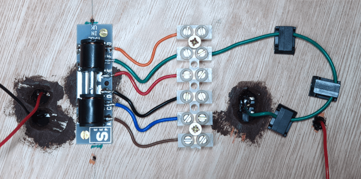
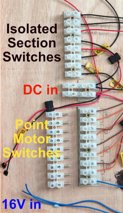
The wires to operate each point motor were installed next. I used blue wires for the 16V power supply and brown and orange for the wires to the switches to ‘throw’ the points. Each motor is numbered (1 to 4) and the switch wires are labelled with white tags (coloured electrical tape).

The power supply to the rails was installed next. Nothing fancy here, traditional red and black wires.

Then the isolated track sections were wired up. Each isolating section has been labelled, this time using yellow labels. They will be connected to on / off switches on a control panel.

So far so good. It’s very colourful but that allows me to figure out what’s what. There’s no point in wiring things up and not being able to understand what you’ve done 🙂
I will use a plug and socket connectors to connect the electrics to a control panel.
After all this work it seemed sensible to test it.
I’m waiting for a 16V transformer so I couldn’t test the point motors, but I could test the track.
As I haven’t made the control panel yet, I wired up the plug conector so that all of the isolated track sections were live.

This is the part where I tell you that it worked first time….
…. but it didn’t !
When I placed a loco on the rack and turned on the controller there was that high pitched noise that tells you there’s a short circuit somewhere.
I spent the next hour working through the possible causes:
- Was there a gap in the copper clad sleeper at the end of the baseboard? Yes, there’s a gap.
- Were the wires ‘dropping’ from the track consistent, with red always going to the same rail and black the other? Yes.
- Had I done the wiring under the baseboard correctly without crossing red and black wires? Again, yes.
- Was the polarity of the frog switching correct? No. Problem found.
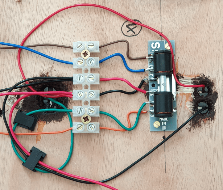
I’d wired the electro-frog on three of the point motors incorrectly. This was easily corrected by swopping the red and black wires into the ‘chocolate block’ connector.
If I’m honest I’ve reread the point motor instructions and I still don’t see why I have had to do this. There’s clearly something I don’t understand about frog switching with SEEPs. I will ask an expert at some point in the future. It’s always good to learn something new.
For now, let’s go back to the original question.
Does the track work?
I’m pleased to say it does….. here’s the contractor’s loco doing a test run.
Yah ! Result !
There’s more electrics to do but this is an encouraging start, and I can breath a sign of relief 🙂

I think you are extremely brave and skilful
LikeLiked by 1 person
Hi Jeremy, Thanks! Brave, perhaps. Skillful, no – it’s just a lot of simple circuits, that the only way I can understand it 🙂
LikeLiked by 1 person
Model railway wiring is a load of simple, identical circuits. It’s only when you do a lot of them that the under-board wires look scary. One at a time, they aren’t so bad.
LikeLiked by 1 person
Looking good Steve! And it works which is the main thing. It is always amazing just how much wiring goes into a small layout. I recall the days of my first train set with just two wires to make it work! As an aside Gaugemaster and some other companies do a three core wire specially for wiring point motors. I have bought some but not used it yet but hopefully it may make my wiring a bit tidier if the three cores are moulded together.
LikeLiked by 1 person
Hi Woody, Thanks! Yes, it’d be nice to go back to a 2 wire layout 🙂 I didn’t know about the 3 core wire, that’s a really good idea. I will look out for that at shows. Thanks for the tip.
LikeLike