With the points (switches) in place it was time to fit the point motors.
There’s very little space under the baseboard, around 20mm (0.8 inch), so I needed some small point motors. SEEP motors are only12mm (0.5 inch) deep and this made them a good choice. I chose the simplest model (GMC-PM2) because the points are insulfrog and there’s no need for frog polarity switching.
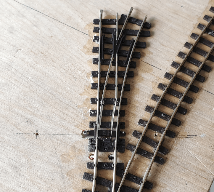
I had drilled the hole through the baseboard for the actuator pin from the point motor already. The next step was to draw a line to mark the line of movement of the point tie bar and drill two small holes through the baseboard, one at each end of the line.
When you turn the baseboard over, you can draw a line between the holes to show the movement of the point.

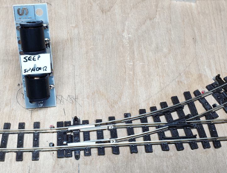
SEEP motors need to be centralised under the point. Michael Campbell has a very neat way of doing this and I used his method. The point blades are centralised by placing a thin piece of plastic between the point rails and the stock rails. The actuator pin is centralised using a piece of plastic wedged between the two coils.
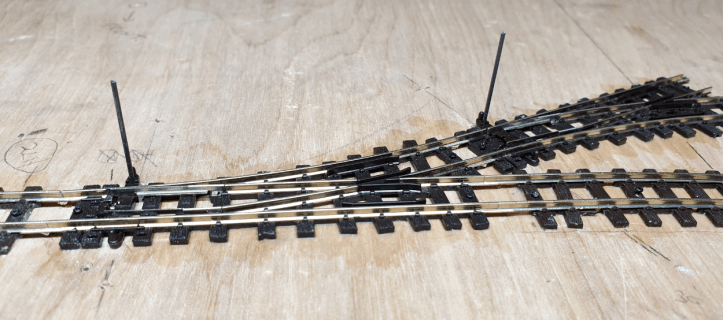
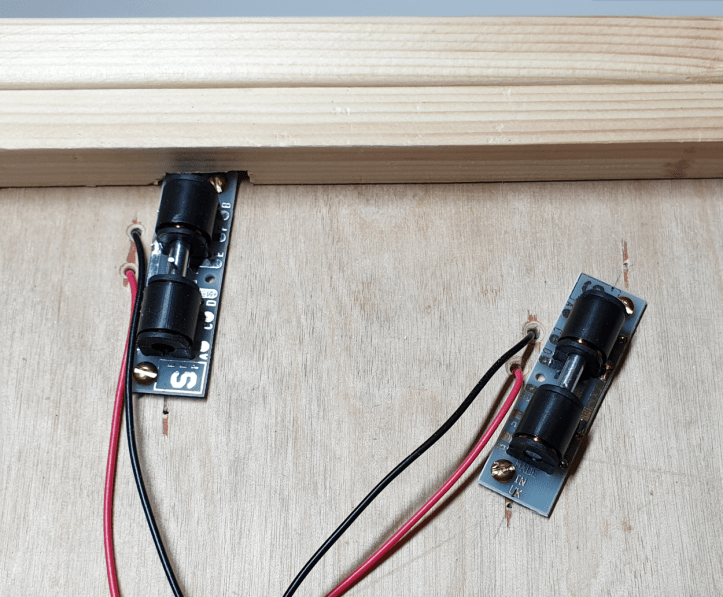
Then the motors are positioned underneath the baseboard. The actuator pin is threaded into the hole in the tie bar. When the direction of movement of the actuator pin aligns with the pencil line, the motor can be screwed in place and the plastic packing pieces can be removed.
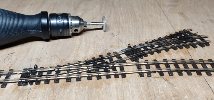
The actuator pins were far too long.
Standard advice is to mark where the pin needs to be cut, remove the point motor, cut the pin and then remount the point motor. I didn’t do this, instead I cut them off in situ using a cutting disc in a mini drill. It worked for me!
One of the point motors is very close to the edge of the baseboard. I modified the frame supporting the baseboard to create some space.
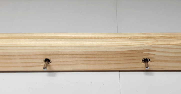
Next I fitted the switches. I wanted them on the front of the APA box, close to the points. It was easy to drill two holes for them.
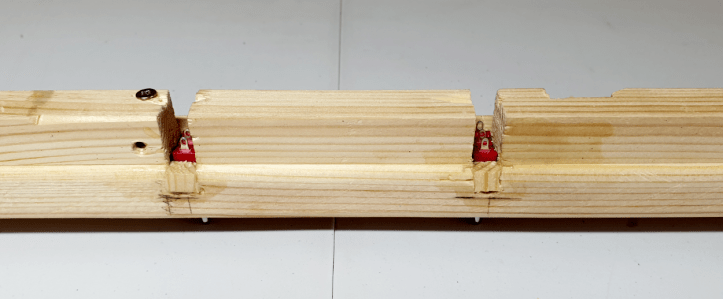
However the switches had to be recessed into the wood to allow the toggle to protude through the front. This was trickier to do, but with a saw, a drill, a chisel and a bit of bodging I managed to do it. It’s not pretty, but it will be hidden from view 🙂
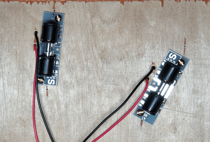
It was time to smell some solder and wire up the point motors. I followed Michael Campbell’s advice and used terminal block connectors so the point motor can be removed easily, if needed.
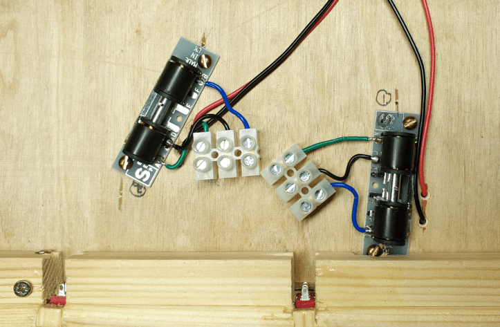
I’m not a confident electrician and I like a simple wiring diagram that I can follow. Luckily, I found Brian Lambert’s very informative website where Brain has included a diagram of how to wire SEEP point motors.
With the diagram, and working one colour at a time, the job was straightforward. I made two small changes. There isn’t enough depth under the board for a CDU so I wired directly to a 16V transformer, and I’d run out of red wire so I used blue instead.
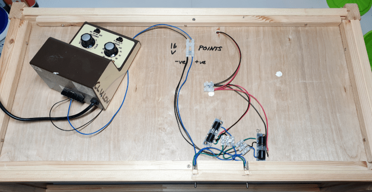
I was relieved when everything worked. Many thanks to Michael and Brian for sharing their knowledge and making my life easy.
I do like the Bzzz-Thump these motors make when they operate.
You flick the switch and you know something’s happened 🙂
